
In colder climates winter storage crops have been stored in passive root cellars for centuries, striking the balance between outside conditions and storage conditions. Although modern refrigeration systems are generally used for large scale, longer-term storage of these crops some enterprises seek lower cost and high energy efficiency options. Outside air exchange systems use an exchange fan to draw colder outside air into a storage room to maintain a depressed temperature. The control of this requires monitoring outside temperature and inside temperature and only allowing air exchange when the outside air temperature is low enough to cool the room, but also only when the inside room requires cooling.
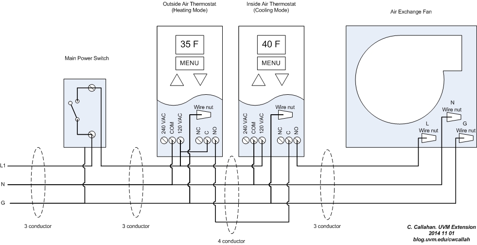
This control can be accomplished with two thermostats wired in series; one setup for heating (outside/colder air) and one setup for cooling (inside/room/warmer air). All thermostats are essentially a switch whose state (on or off) is controlled by a temperature sensor and a setpoint. They are either purchased or configurable for heating (turn on the load at or below a setpoint temperature) or cooling (turn on the load at or above a certain load). In our case, we are using a heating thermostat “cascaded” to a cooling thermostat so that our “load” (fan) only comes on at or below a certain outside temperature and at or above a certain inside room temperature.
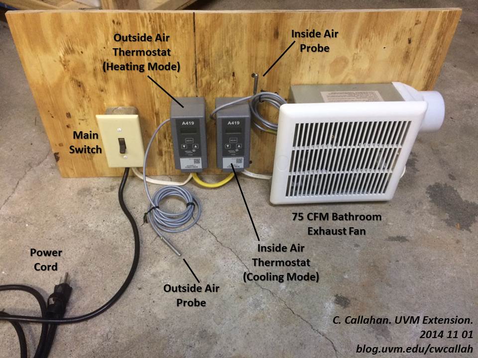
In this system (a mockup used for cold storage workshop instruction) I used the following items:
QTY 1 – Standard Light Switch – $0.69
QTY 1 – Switch Box – $0.91
QTY 2 – Johnson Control A419 Thermostats w/ 6.5 ft probe (one setup for cooling, one setup for heating) – $58.95 each ($117.90 total)
QTY 1 – 50-100 CFM Bathroom exhaust fan – $25-50
Misc 3 and 4 conductor 14 AWG solid wire.
Total parts: $145-170
Total time: about 2 hours for first build.
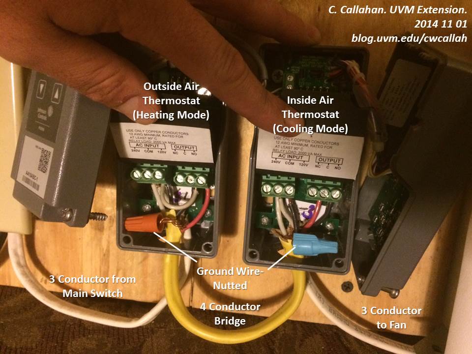
A note on thermostats. I like a digital thermostat with a remote probe and I tend to use the Johnson Control A419. It has a 1 degF setpoint resolution and down to 1 degF differential. Each one can be setup for heating or cooling by making the proper adjustment of dip switches inside the box (see p.7 of the manual). Ranco make a similar thermostat in their ETC line. I’m still on the lookout for a good, inexpensive delta thermostat (a thermostat that controls a load based on a true delta-T, or temperature difference, between two locations.) Most are designed for solar hot water systems and don’t seem to allow for control at lower temperatures. And they are fairly expensive.
I ran mainly 3 conductor wire in this setup, but did find the 4 conductor wire to be a clean way of getting an additional wire from the first thermostat to the second. This allows for both thermostats to be powered regardless of the output state of the first. This lets the user see both measured temperatures and make setpoint adjustments since both thermostats are always powered whenever the main power switch is on.
The basic settings for each thermostat in this setup were:
| Outside Air Thermostat |
Inside Air Thermostat |
|
| Jumper 1 | JUMPED (Heating) | OPEN (Cooling) |
| Jumper 2 | OPEN (Cut In at SP) | OPEN (Cut in at SP) |
| SP (Set Point)* | 35 degF | 40 degF |
| Diff (Differential) | 1 degF | 1 degF |
| ASD (Anti Short Cyle Delay) |
1 min | 1 min |
| OFS (Offset for BIN) | 0 – Not used | 0 – Not used |
| SF (Sensor Failure Operation) | 0 (De-energize) | 0 (De-energize) |
* – Note the outside air thermostat should always have a lower setpoint (SP) compared to the inside air (room) setpoint. This is what ensures the fan only comes on when the outside air will actually provide cooling.
A note on sizing the fan. Moving air works out to about 1 BTU/hr per degF per CFM (or ft3/min).
Why?
Specific Heat of Air: Cp_air = 0.24 BTU/lb/F
Density of Air: Rho_air = 0.07 lb/ft3…
Q_dot {BTU/hr} = V_dot {ft3/min} x Rho_air {lb/ft3} x Cp_air {BTU/lb/F} x (Tin – Tout) {F} x 60 {min/hr}
which all works out to
Q {BTU/hr} = 1.008 {BTU/hr/CFM/F} x V_dot {ft3/min} x (Tin – Tout) {F}.
So with a 75 CFM fan and a 10 degF temperature difference, this system can cool at a rate of 750 BTU/hr. Large fans or multiple stages are even possible. Watch the amperage of the load compared to the thermostats, though. You may need an intermediate relay to handle higher current in larger systems.
Be careful of drying out or freezing whatever you’re cooling. When you bring air in from outside, especially when cold out, it will generally be more dry (lower relative humidity). So you’ll want to keep track of humidity and may need to add some to the air.
Cross posted on FarmHack.net, join the discussion. Download a fact sheet on this tool.